Finite Element Analysis is a technique in which a computer model or a prototype is made of a material with a proposed design, and is then tested under various conditions it might experience when in operation. This technique is used by companies and extensively by engineers to meet client based design requirements. It is used in designing new products and in refinement or modification of existing products or designs as well.
The purpose of this discussion is to basically introduce Finite Element Analysis and how to use it on a 3D CAD software CATIA V5. CATIA V5 is an open source 3D solid modelling application developed by Dassault Systemes industry wide known for its use in developing sheet-metal, mechanical and aerospace design and parts.
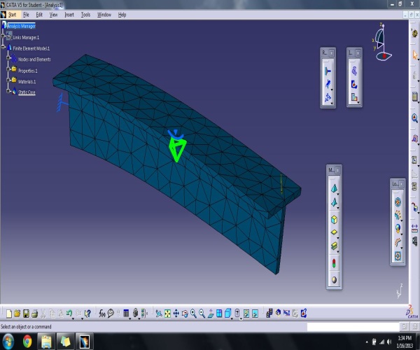
Here an analysis of a cantilever beam with a “T” cross-section has been done which experiences a load of certain amount. The video below shows how that was done. Based on the results, the beam analysis conclusion was done in the end.
The photos below show a glimpse of some of the important aspects that can be used in CATIA V5.
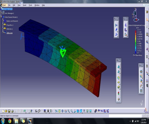
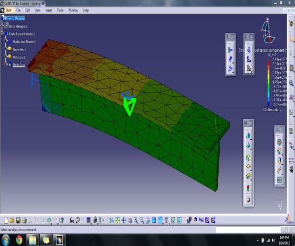
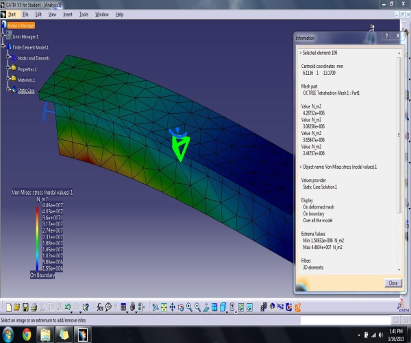
From the above analysis done, it was found that the maximum von Mises stress occurs at the point shown in red in Image 4. It was also found that the maximum stress value at that point was less than the yield strength of the material used which in this case is steel. From this, it can be concluded that the material of that geometric specification will be able to sustain the loading. It was also found that the material showed some deformation, which means that even if failure occurs after consecutive load cycles, the material shall show warning prior to yield.
This basic example provides information on how to get started using Finite Element Analysis on CATIA V5. Further discussion shall showcase use of Finite Element Analysis in various engineering applications.